Holemaking in sheet metal: Laser cutting or punching machines?
Punching machines were once the de facto choice for holemaking, but does that still hold true?

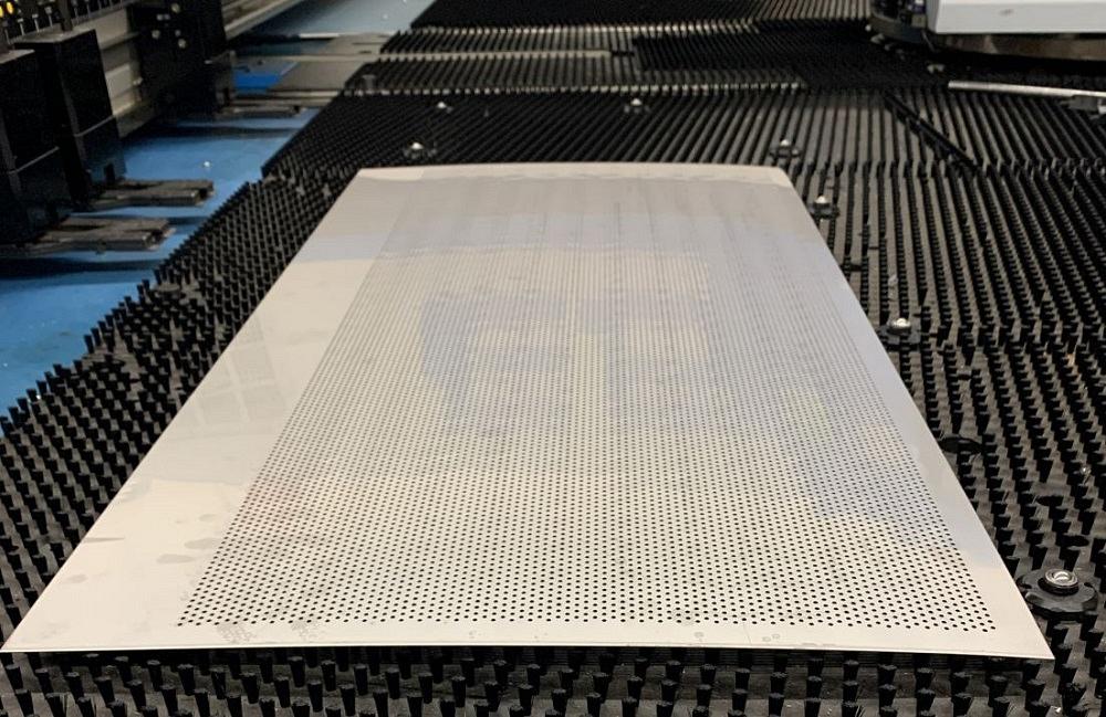
FIGURE 1. When it comes to holemaking, a punching machine still stands out for its ability to generate a large number of holes in a short amount of time.
A lot has changed in metal fabricating over the last 30 years, particularly when it comes to holemaking in sheet metal. In the 1990s the punching machine was the only way to go, until the emergence of the CO2 laser cutting machine changed the nature of the conversation.
By the 2000s, laser cutting technology was ready to take off. During the early years of the 21st century, punching machines still remained a competitive option for fab shops, particularly if they were delivering a multitude of holes to a sheet metal blank and forms that could be duplicated only in a press or press brake.
It wasn’t until the advent of fiber laser cutting technology in the 2010s that longtime fabricators had to rethink their approach to holemaking again. These solid-state lasers could rip through thin sheet metal at a speed that made the CO2 lasers look antiquated.
Now fiber lasers have reached 20 kW in power, and they are cutting thicker materials at speeds few would have expected when the technology first made its debut. Laser sales are expected to grow at an accelerated pace in the coming years as metal fabricating companies try to keep up with the technology advances. But where does that leave the punching machine when it comes to making holes?
Of course, punching still has its place. It’s versatile. Shops can create forms like louvers and embosses without having to move them to another machine. A punching machine also is generally less expensive than a fiber laser cutting machine.
But punching machines still stand out as holemaking workhorses for those applications where small holes need to be created consistently and quickly (see Figure 1). For these types of applications, punching might be the most economical way to produce holes.
Making Many Holes
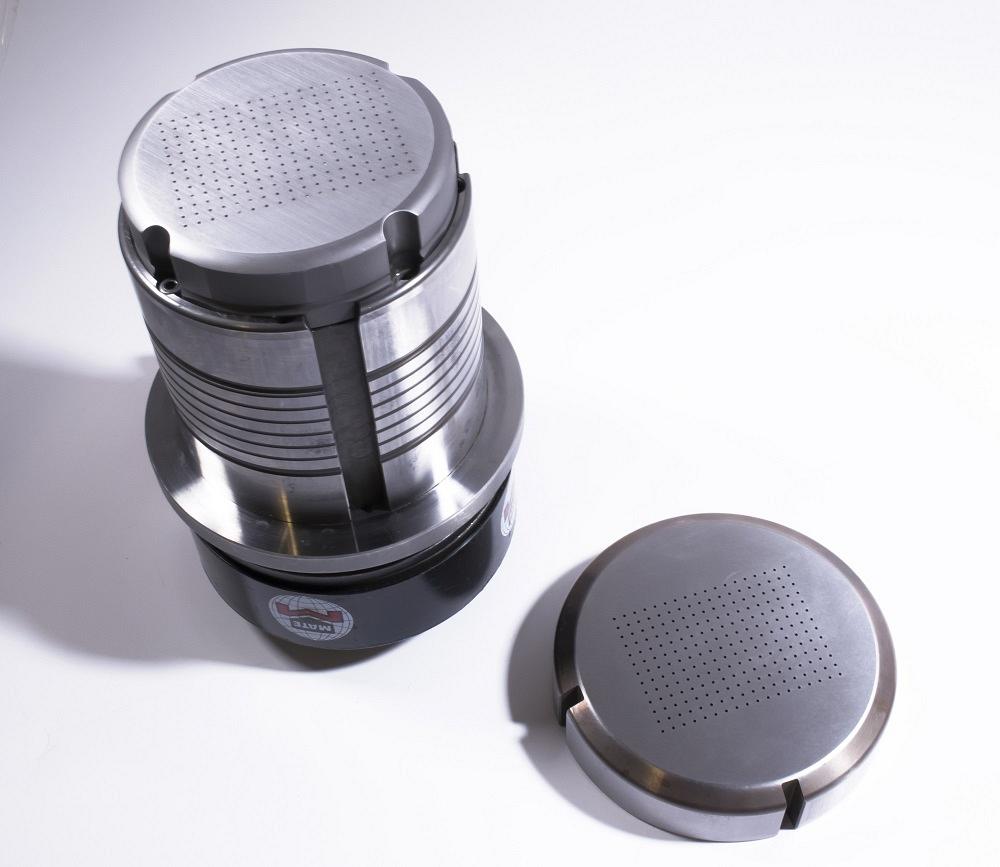
Consider the production of perforated screens, for example. Cluster tools typically are used for punching these hole patterns as multiple punches can be used in one tool, maximizing the number of holes created in a single hit (see Figure 2). Imagine one punch having as many as 234 pins and creating that many holes with just one stroke! It’s been done.
Many different punch designs and cluster areas also are available, providing many punching choices. For instance, you can use a tool with a hexagon shape to create hole patterns with angles and add visual interest to the screen.
Keep in mind that for cluster punching, the punching machine has to be able to deliver the required amount of punching force for the application. The maximum recommended punching force should not exceed 75% of the press capacity. The following formula can be used to estimate the required punching force:
Linear length of cut x Material thickness x Shear strength = Punching force in tons
FIGURE 2. A cluster punch is an effective way to punch holes with one stroke. This is a 234-pin, fully guided cluster set.
The linear length of cut is equal to the hole perimeter multiplied by the number of punches in the cluster. The hole perimeter for a round hole is 3.14 times the diameter. The hole perimeter for a shaped hole, like the hexagon, is the sum of the lengths of the sides.
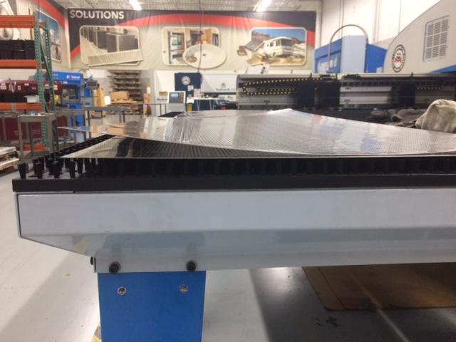
When you are punching a sheet with a lot of holes in it, the sheet is going to want to curl upward because of the amount of force and stress put into it in the punched area (see Figure 3). For this scenario, you can use domed dies that will help to counteract the curling. How does this work? A stripper with a concave shape moves downward with the stroke and actually flexes the sheet downward over the domed die, which counteracts the upward curl that comes with the punch.
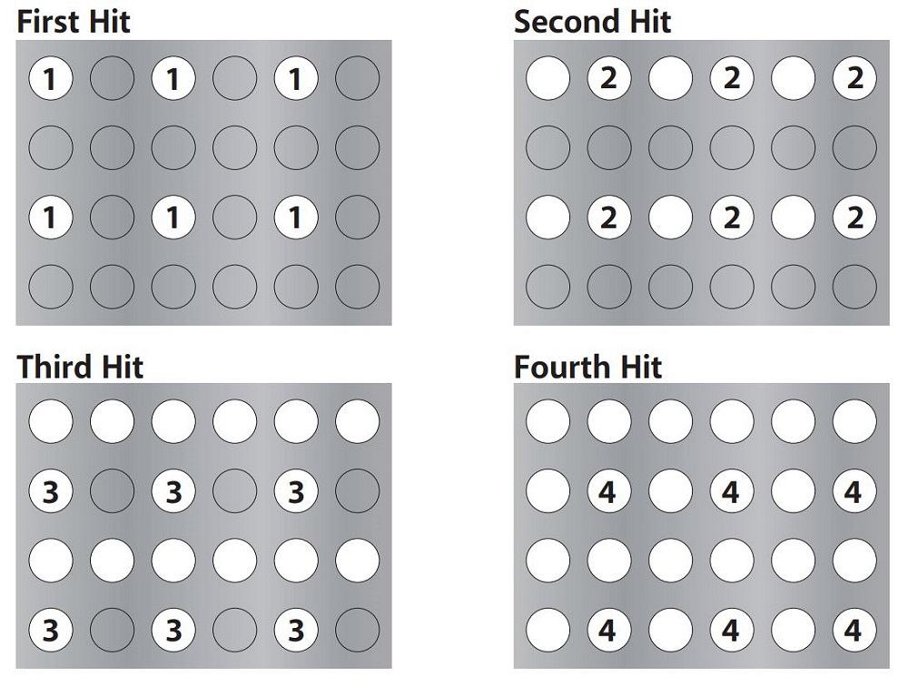
For greater uniformity while also helping to keep sheets flat, the punching pattern can be altered to avoid concentrating all the punched holes in one area (see Figure 4). By repeating the pattern, an area can be filled with holes with the same number of strokes but without the extreme pressure being applied to one area to complete a hole pattern.
For those applications in which the material presents a holemaking challenge or the punches are being used repeatedly, shift after shift, fully guided cluster punches are extremely helpful. In this situation, the stripper clamps material to the die during the entire length of the stroke so that it can support the punch as near to the tip as physically possible. Without this type of support, especially in jobs where the punch is narrower than the material thickness, the punch is vulnerable to lateral forces that could bend the tip. If the punch is severely abused in this manner, it bends far enough to shave the die, damaging both tools. (As a rule of thumb, you should never nibble off a strip narrower than 2.5 times the material thickness.)
Making Single, Clean Holes
Sometimes you might only need a limited number of holes, but they have to be of very high quality. That’s where a punching machine can stand out as well.
Take, for instance, when a threaded hole is required. In an application like this, there is not a lot of room for error. Typically, when a punch is used to create a hole, the sides will be very straight until the very bottom of the hole where the fracture of the material occurs. The bottom of the hole is going to be a little bit bigger than the rest of the hole because of that fracturing. A punch and a shave can change that dynamic and create very precise results. When this combination of tooling is used, the punch is slightly smaller than the final hole size. After the holes are created, another, slightly bigger punch is used with a tighter clearance to shave down the walls left by the previous punching action. The result is a straight wall all the way through the hole, which allows for much more of an opportunity for thread engagement when the tapping occurs.
When it comes to making these holes, you should be aware of some guidelines as they relate to the ratio of punch to material thickness:
For Nonguided Tooling
- Aluminum: 0.75-to-1
- Mild Steel: 1-to-1
- Stainless Steel: 2-to-1
For Fully Guided Tooling
- Aluminum: 0.5-to-1
- Mild Steel: 0.75-to-1
- Stainless Steel: 1-to-1
How do you apply these guidelines to punching action? If you are punching 0.078-in.-thick aluminum, for example, you should punch a hole with nonguided tooling no smaller than 0.059 in. With guided tooling, the punched hole shouldn’t be smaller than 0.39 in.
FIGURE 3. The top sheet shows just how much sheet metal will curl if steps are not taken to address it during the punching process.
You also have to be aware of where these holes are being punched. Holes in the wrong place could distort nearby holes and shapes. In general, there should be two times the material thickness between holes and two times the material thickness between holes and the sheet’s edge.
One more reminder: If you have good alignment between the punch and the die and the right die clearance is selected for the material type and thickness being punched, the results should be acceptable. And the tooling will last longer than if it were being abused.
The Hole Story
Punching machines have a rightful place in the modern fab shop. They can deliver scores of holes in a matter of seconds and can provide high-tolerance holes that can be hard to duplicate with a laser.
But it doesn’t end there. The machines are better suited for efficient processing of small parts. When the final blanks are separated from the skeleton, they can be sent down the punching machine’s chute or collected in the scrap bin. If the part is not attached to the skeleton while it’s on the bed of a laser cutting machine, it can fall through the slats and then be subjected to the laser spatter and debris that comes from the laser cutting process.
While a lot of the focus is on high-powered fiber laser cutting machines today, punching machines have advanced as well. They process sheets faster than previous generations of the technology, and they have fast ram speeds, increasing the number of punching hits that can be made per minute. Some machines can punch as fast as 1,350 strokes per minute.
But discussion of speed is just part of the conversation. If the focus is on throughput, the punching machine is hard to beat. It can form, scribe, and tap, helping you to avoid other downstream processes. That’s the whole story when it comes to the punching machine.
Publica tu anuncio gratis /publish your ad for free


